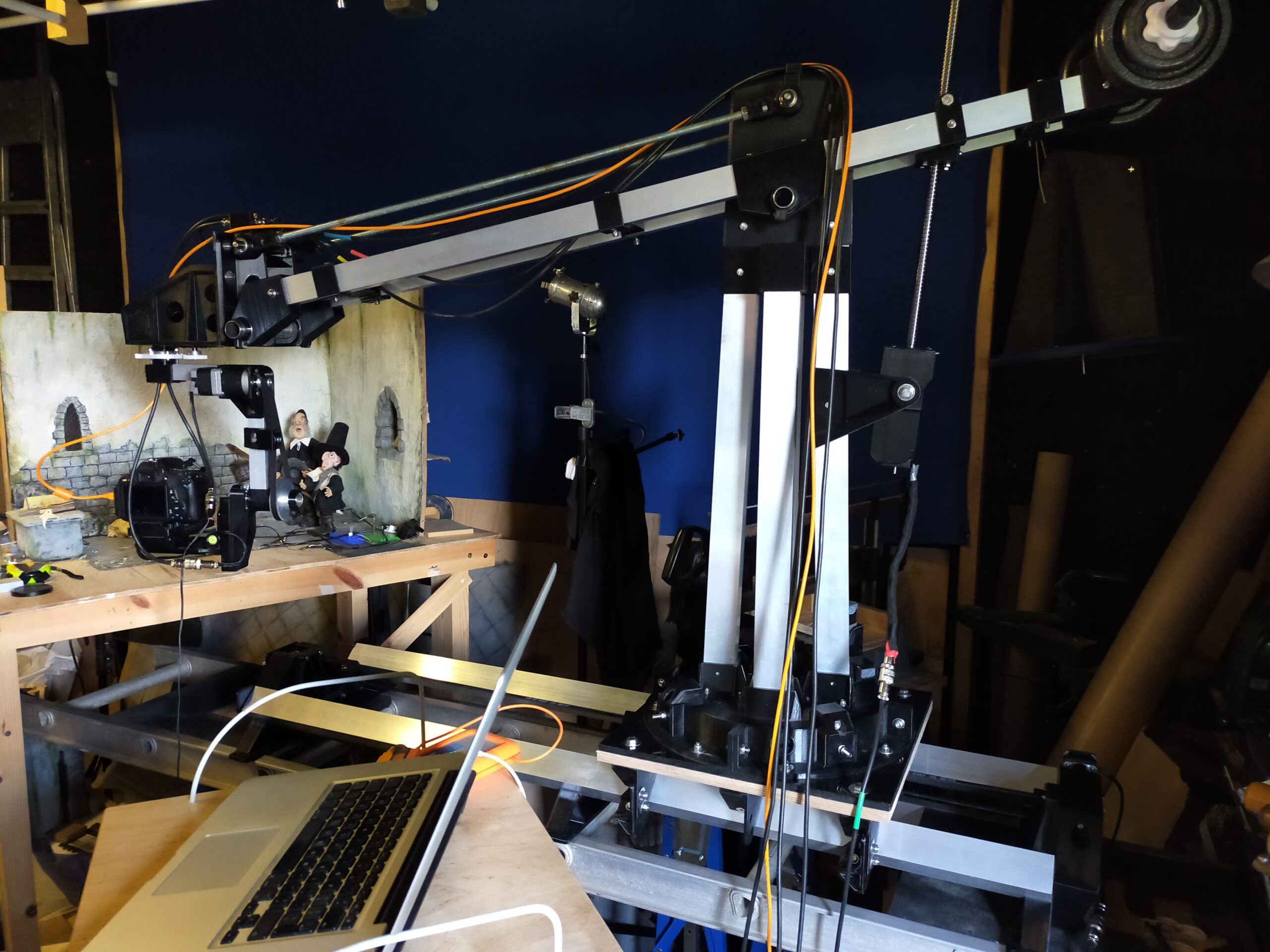
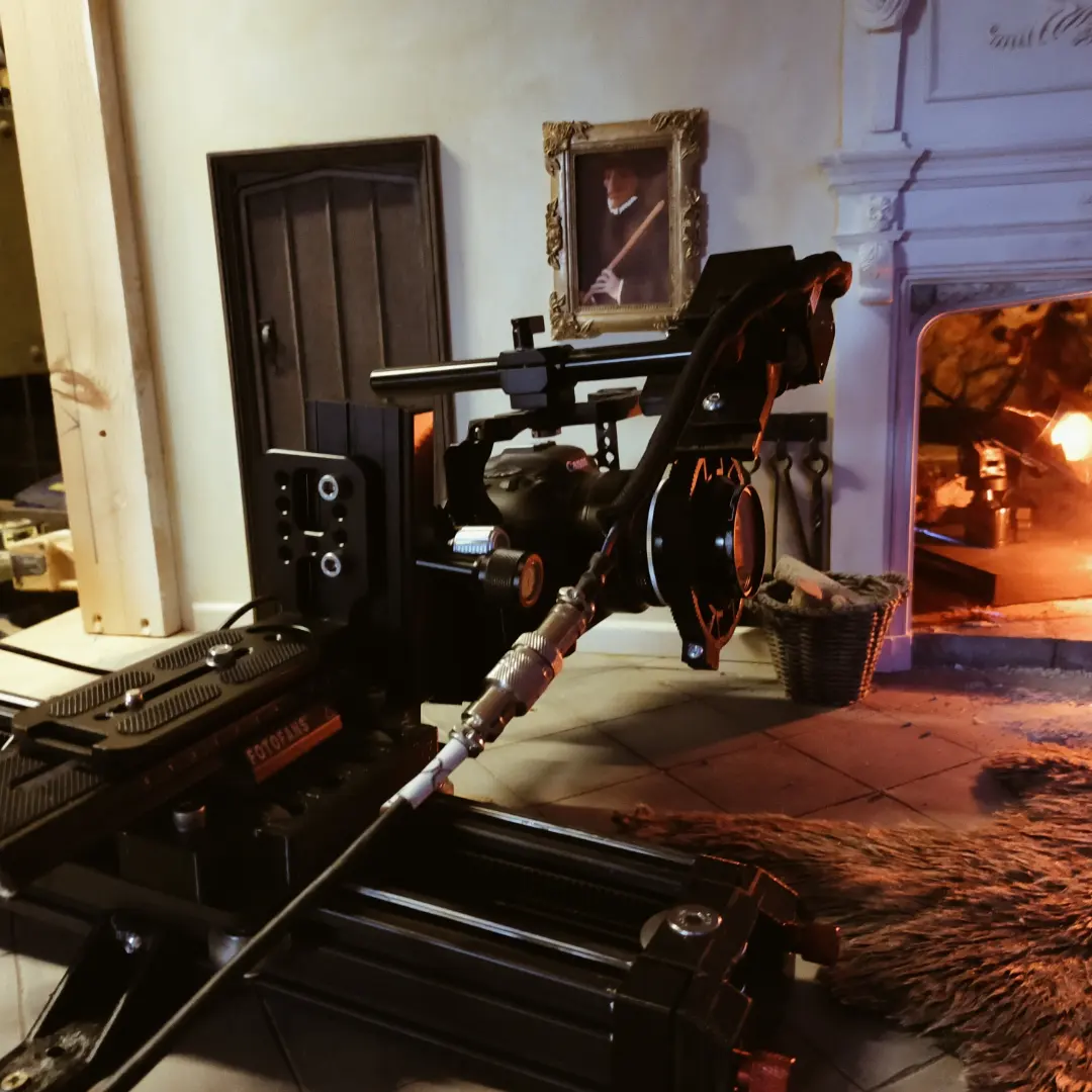


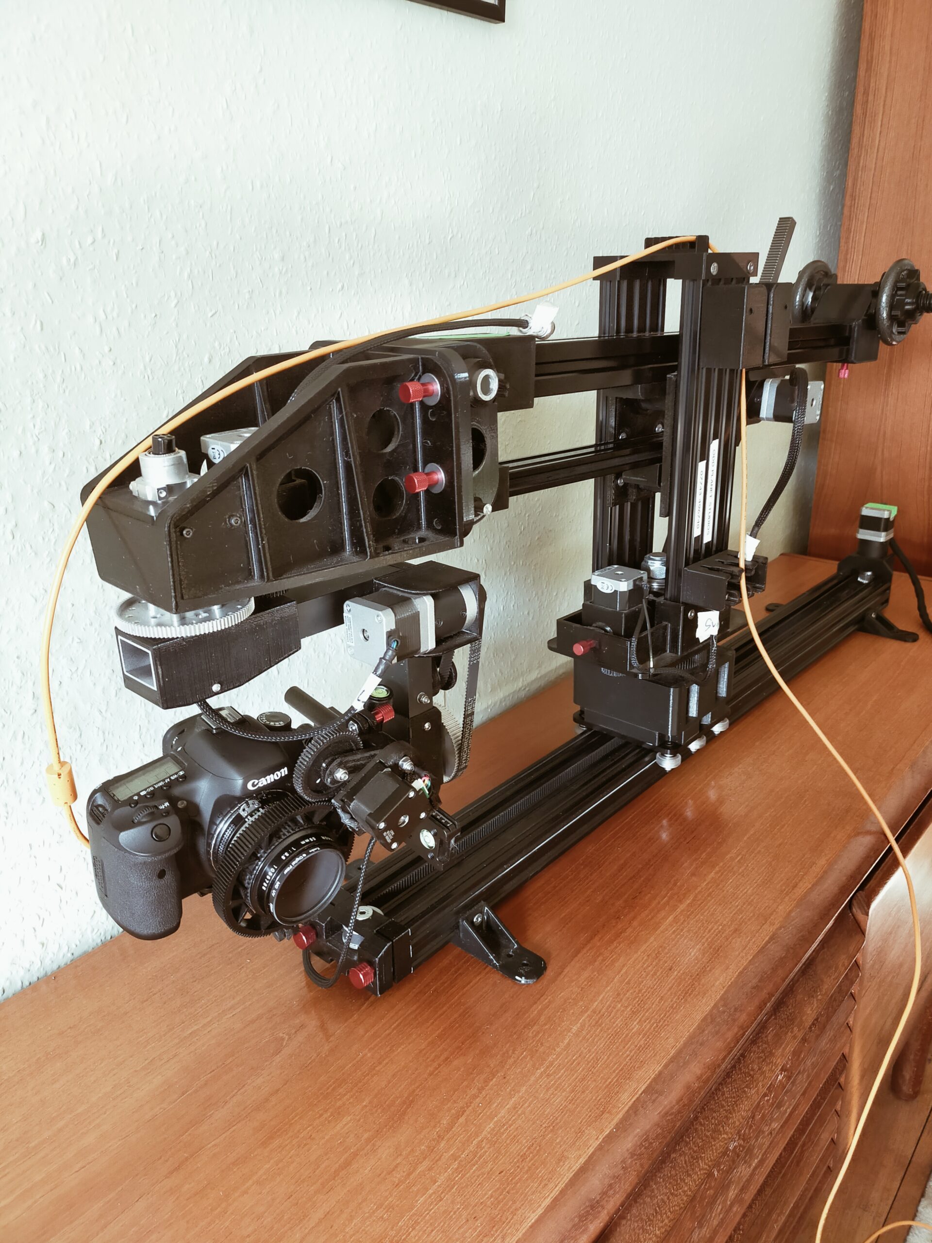
Moving the camera by hand for stopmotion is not easy, especially when a move involves more than one axis. A motion control rig enables complex shots to be controlled from Dragonframe’s ARCMoco software via an Arduino board. The computer calculates the increments for each motor and moves them the exact distance for each frame, so the results are smooth.
Having researched what is available commercially, and found it very expensive, we decided to construct a bespoke rig. This uses readily available stock parts, and will control 6 separate axes simultaneously. These are:
Track – Rotate – Jib up/down – Pan – Tilt – Focus
The only axis not covered is Roll, but this can be achieved by turning the camera 90 degrees on its mounting platform.
Track
The dolly uses 8 skateboard wheels running on a 2m alloy ladder, and is controlled by a ballscrew. A Phidgets 1:5 geared stepper motor drives this.
Rotation
A vertical post is mounted on the dolly, and the top section of this rotates to swing the jib arm. This is driven by a 1:27 geared stepper motor through toothed gears 30:125. These were chosen simply to have the largest gear I could find to make mounting the motor easy.
Jib up/down
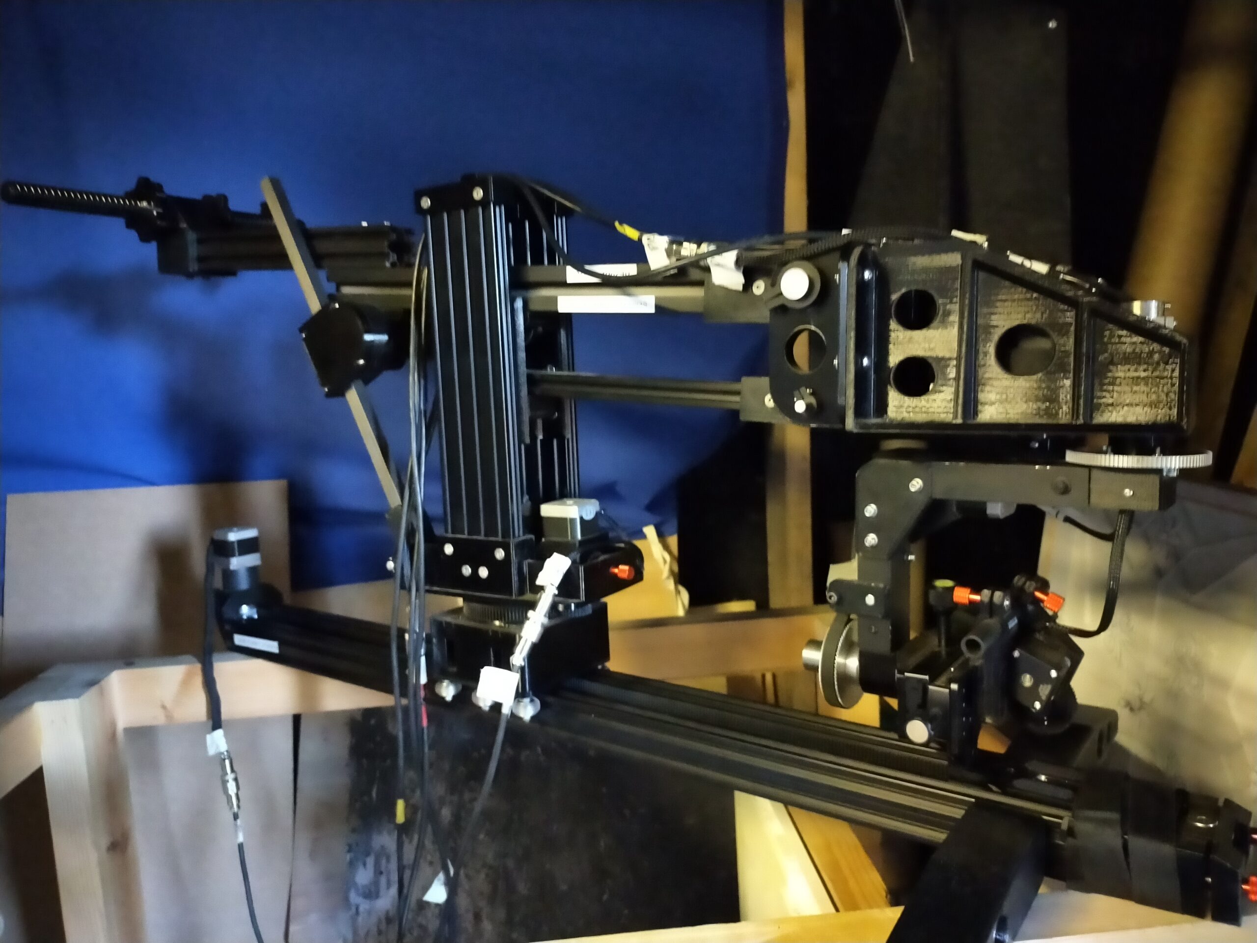
The jib arm is attached to the rotating section and controls camera height. The reason for using a jib arm is that a vertically sliding pedestal is much more complex to design and build. The jib arm is balanced by weights.Crane motion is provided by another 1:27 geared motor driving a toothed belt, as this enabled me to mount the motor at a distance from the fulcrum. The motor is mounted on a sliding plate that tensions the belt.
Pan
Panning is achieved using an L-shaped arm mounted on a short vertical bearing.
Tilt
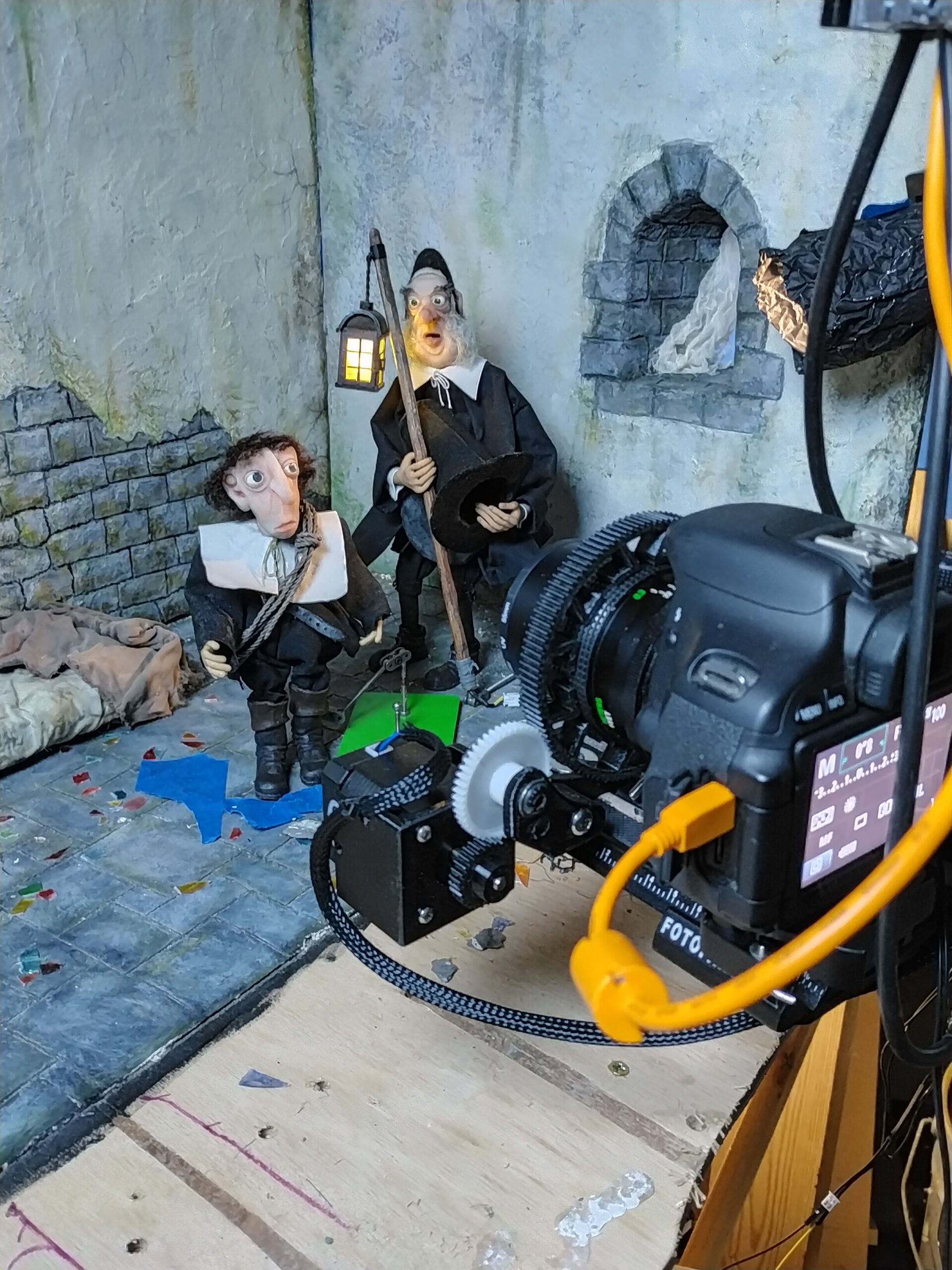
A horizontal bearing attached to the pan arm rotates the camera up and down. The camera itself sits on an adjustable platform so that it can be balanced and rotate around the axis of the film plane.
Focus
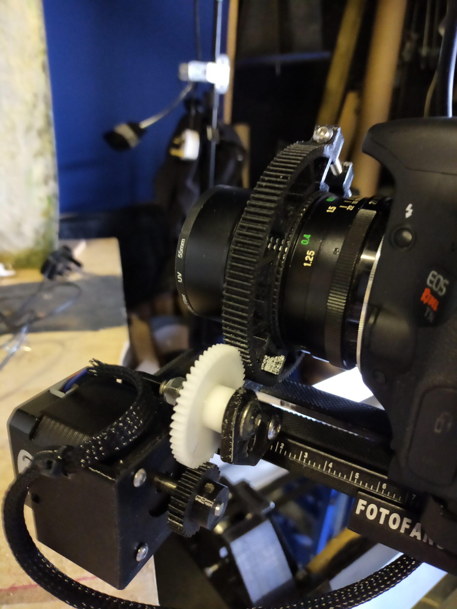
Not strictly an axis, but essential. The focus is controlled by a small stepper motor on a plate attached to the camera platform, driving a gear that meshes with a flexible rack fitted onto the lens focus ring.
Control
Stepper motors need to be controlled by drivers, which are small powered circuit boards. The Big Easy Driver is robust and relatively simple, one is used for each of the motors.
An Arduino Mega 2560 translates the computer instructions into motor movements. This is connected directly to the computer and user control is via the Dragonframe program. Each move is able to be divided into increments-per-frame, eased in and out, and operated simultaneously with any other motors. Once a camera move is set up, Dragonframe shifts the camera for each frame, leaving the animator to concentrate on moving the puppets.
Blog posts will give details of construction, and the challenges along the way!
Bearings
The accuracy of the rig clearly depends on having bearings that are robust, free-running and have very little play. Large diameter bearings are superior in this respect to smaller ones, so we have opted for 1” (25.4mm) bearings from Servocity with hollow aluminium shafts. The bearings come as pillow blocks that can be mounted onto alloy box sections, although we glued them in place.
Additionally a thrust bearing is needed where the vertical post is mounted on the dolly.