Moco Rig 7 – March 2017

I wish I could say I have made a lot of progress recently, but sometimes thinking about what to do is the most important thing. I knew I had to come up with a better rotation bearing – a lazy susan – but couldn’t seem to get it right. Now I have a solution, so some visible progress should soon happen!

Basically, there will now be a 400mm diameter disc resting on 14mm stainless bearing balls, which are held in position with a simple cage, a flat disc with oversize holes that permit the balls to rotate easily but hold them in alignment. The disc will rotate on a central spindle. It will be held down by some bearings on brackets mounted around the perimeter. In order to have a flat surface for the balls to move on, I am using some polycarbonate that I have available. This is probably not the ideal plastic, being a bit soft, but it is what I have. So the change from the previous post is that I have eliminated the need for machining a groove, and have a better running surface.

Around the perimeter of the disc I will mount a flexible plastic gear strip (1.0 MOD) that will engage with the motor’s pinion, and should give nearly 180 degrees rotation in each direction. I have not been able to find (at a reasonable price) either large pulleys or gears that would do the job, but as long as the strip can be firmly attached, it should be fine.

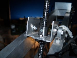
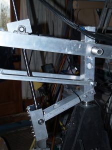
On top of the disc (birch ply screwed to the polycarbonate running surface) the whole crane is mounted. This can now incorporate the support for the ballscrew that raises and lowers the arm, increasing rigidity and therefore accuracy.

Although I am pretty confident that this will stop the stiction problems, inevitably someone else seems to have come up with an even better solution. Edu Puertas has posted a YouTube video of improvements to his rig, in which he changed from a ballscrew for jib arm raising to a straight linear rack. This was because he was experiencing some side-to-side wobble caused by friction with the ballscrew mechanism. It seemed to me that it was amplified by his choice of attachment point, right at the camera end. My ballscrew not only is nearly upright, but is attached at only around 250mm from the fulcrum, so I think this may not be an issue for me.

But I won’t find out until it’s made, so here goes….

PS The ungeared stepper motors I tried last month just wouldn’t pull the load on the pan and tilt. Maybe it was down to me trying to move them too fast, not sure. So I have gone back to the geared ones, and just have to live with the backlash in the gearboxes. I need to improve the adjustability of the motor mount so I can get the closest possible meshing of the gears. Another little job!
Moco Rig 6 – Feb 2017

Having successfully upgraded the crane function to a ballscrew, my attention has turned to the rotation. I was always a bit unhappy about this, as the gears are quite small and the arm is long, with lots of inertia. It worked for my tests, but seems a little jerky in action – stiction taking control!

I have decided to upgrade. The dolly itself could benefit from being rebuilt, as I used standard WBP plywood for the original, which is not great stuff. So I will rebuild using 15mm birch ply. At the same time the bearing and drive will be changed. These will now have a 450mm diameter ball race, routed directly into the ply and using 20 14mm dia bearing balls and a cage made from hardboard.  I found a youTube video on making a wooden lazy susan bearing, and this seems to work well. The big diameter should make for a very stable platform – another case of my converging on standard design after trying the alternatives!

To prevent the dolly from tipping up I shall reuse the original thrust bearing and post to locate the dolly. Around the perimeter of the dolly top plate a flexible gear rack will be fitted, meshing with the gear from the motor, mounted on the dolly base. This will give a much better ratio, less effort required to turn, and goes a long way to overcome the inertia issues. Pics as soon as I have constructed the modifications.

Additionally I have changed the geared stepper motors on the pan and tilt axes to ungeared motors. This will eliminate the backlash at these points.

And the Big Easy Drivers have finally exhausted my patience! For no apparent reason another stopped working. Probably nothing wrong with the units themselves. It is the connections that are proving so tricky. The green screw-in connector blocks that fit onto the BEDs have holes that are almost too small for the motor wires, so they are ridiculously fiddly. I have retired them all and gone for the black box CNC type (nice easy connections!), 3 of which are working perfectly at the moment, 3 more on order.

With luck these modifications will finally give me the accuracy and repeatability I need.

Moco Rig 5 – end Jan 2017

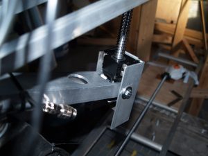
I finished the modification to the crane axis over the weekend, and it is looking good. The motor is now mounted on a swivelling carriage that also has the bottom bearing for the ballscrew. On the arm is another swivelling carriage with the ballnut attached – that’s the bit that travels up and down.

top carriage connecting ball nut to arm

showing support extending from pillar

motor and bottom bearing carriage (motor absent)


Result: no play at the camera end! This is going to be really solid.

Important thing about positioning the screw seems to be to get the angle close to 90 degrees when the jib arm is level, and to avoid any acute angles at the extreme ends of travel. It required me to attach an extension arm to the bottom of the rotating pillar so I could achieve this. I have seen rigs where the motor carriage is attached close to the pillar, but I think mine is superior.

Yet to test it out as I am waiting for a solid 8/10mm coupler to arrive from China!

First shot and making thatch

At last a shot completed! The silhouetted hounds of hell rising up from behind the reeds with their eyes flashing. Achieved using small torches mounted on the rig, and each hound attached to a vertically-mounted winder. The moco rig tracked in nicely to give the shot a bit more movement and a sense of foreboding. The first still has just the blue screen background, but the second has a sky inserted and slowly panning across. I had some difficulty with the low light I used to pick out the foreground. It seems that dimming even tungsten lights causes them to flicker noticeably. So in future it will need to be ND filters, or low wattage lights.                         


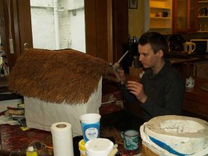
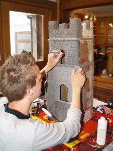
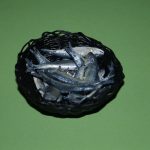
Here are a couple of pics of set construction from last year – building the church and a thatched cottage. Papier-mache pulp was used extensively, and sculpted into stone shapes once it had partially dried. Pine needles form the thatch for the roof, but took ages to hot-glue in place.

Attaching the pine needle thatch in bunches with hot glue.

Leon sculpting the papier mach pulp on the church tower.

Early days – 2017

This is the first of my occasional posts on progress with the project.
It has been nearly 4 years since I first thought about making the film, and much of the time has been spent learning the craft, building a studio/workshop and constructing a moco rig (see posts on the Studio page). During this time I have refined the screenplay, done scene breakdowns and have engaged illustrator Marius Legge to do a complete storyboard. The labour of puppet, prop and set construction goes on apace.


Now we are almost ready to shoot in earnest. I managed to start the year with a simple shot of the silhouettes of the Hounds of Hell rising up from behind some reeds, accompanied by a slow camera push-in, and it feels good to have got one shot in the can. Not edited yet. There are several other shots already done, but that was some time ago!


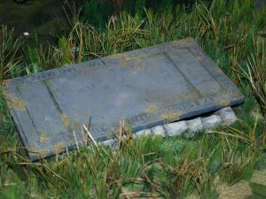
Current plan is to get the moco rig working fully, then do a shot of the graveslab being mysteriously moved aside. These shots will all form part of our teaser trailer, to be released this year all being well. (UPDATE September 2018: Vain hope! The teaser trailer is still not done, although we are much closer. This year!)

In the meantime I have been sculpting and casting silicone heads and bodies as needed, including 3 different stages of Tregeagle’s decline.
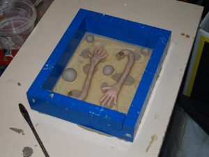
Came across a great tip for creating moulds around fingers. This is to set the hand so that all fingers are horizontal, then use gelatine to fill the lower part of the mould (instead of soft clay, which risks damaging the sculpt). When the gelly has set plaster can be poured/brushed in to form the top half of the mould. The gelly inevitably melts during the plaster set, but can be washed gently away, leaving a nice edge around the fingers. Only issue is a slight meniscus effect, making the plaster edge a little vulnerable. This might be overcome by adding a little washing-up liquid to break the surface tension.

sculpey arms half immersed in gelatine with clay keys

Moco Rig 4 – Jan 2017

I have been very slow in adding posts to this, as it has taken so long for me to get round to creating something that actually functions at all. But the resolution for 2017 is to do a post at least once a month!

The rig as built has been functioning, but there are definitely improvements to be made. Firstly, the drivers. It seems the Big Easy Drivers are fairly basic and quite old in design. They have no protection against overloading, which is why I have managed to blow 8 of them! Newer designs are readily available as drivers for 3D printers and CNC machines. They have black boxes and green connection blocks on the side, and come in several different types. All apparently have optical isolation which separates the signal circuits from the higher voltage power circuit. Phew! I chose one which offered more than 2A current, and there are microswitches on the side to specify the current for the motors, which should be around 1.7A.

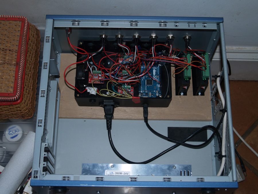
Attached 2 of these, and only one is currently working. Not sure what has happened with the other, but it is more likely a connection fault than anything else. The 4 BEDs that are still working seem fine, so nothing to change there. Also, I have stripped out an old desktop computer to use the box. This means I can put the mains transformer and all the Arduino stuff in one box.

Power supply at bottom, original box with arduino and BEDs at top

Incidentally, I found a fault with one of the Aviation sockets when testing them with a multimeter. The resistance seemed suspiciously low across a couple of pins, so I replaced it. Might have been the cause of several BED deaths!

The mechanical aspects of the rig have also got teething troubles, but that is hardly surprising.
Track, operated with a ballscrew, is slow in operation but has absolutely no backlash. Very pleased with this as a choice.
Rotation is geared. I could not find the huge diameter gears seen on some rigs, so have a MOD 0.8 128 tooth gear from Servocity on the pillar engaging with a 30 tooth pinion on the 27:1 geared motor. There is a sliding mount for the motor, to disengage the gears, and it is held in place with nuts and threaded rods. Crude but efficient. I think the only problem with this axis is that I have set the motor speed a bit fast.
Crane is giving the biggest headaches. The arm is quite big and counterweighted, so there is a lot of inertia. I went for a belt drive, thinking this would be fairly simple. BUT… at first I connected the pinion directly to the motor shaft – not clever as tensioning the belt puts lots of strain on the gearbox. So I added a couple of bearings and attached the motor with a flexible coupling. The result seemed to be even worse, until I realised that the flexible coupling acted like a spring and needed to coil before powering the belt. So I have ordered a solid coupling…..I am sure this is all very basic to any engineer, but I’m just a filmmaker!
However, I am not sure the coupling (yet to arrive) will solve all the issues. There is still a little stretch and bounce in the belt, and of course this is magnified by the length of the arm, so there may be about a couple of mm wobble at the camera end – unacceptable!
I have seen several, including professional rigs, that use a vertically mounted ballscrew. My experience with the track mechanism suggests this is the answer. It will also help to support the weight of the arm. Now I just have to figure out a way to attach it and the motor.
Pan seems to work just fine, although with the new driver there is a buzzing from the motor. I think I need to reduce the current at the driver to see if it stops.
Tilt works perfectly!
Focus has never worked yet! I had a very small NEMA 11 motor, then swapped it for a NEMA 17, but the driver let me down. Back to testing.
The bearings and the general construction has been very successful. I took trouble to make sure everything was as solid as possible with no slop, and this is critical if the rig is going to function as it should.

I have done one shot using the track function, and it has been a delight to do. Not having to think about the camera once it was set up made it so much easier, and we were able to concentrate on moving the puppets.

Moco Rig 3 – Autumn 2016

Hard to believe it has been a whole year… but I have constructed a new shed/studio to put the rig in, and so took a break from development. Now it is up and working, with alloy wheels, that move very smoothly along the track. The ballscrew causes the dolly to move quite slowly, but is really slop-free. It’s not a problem when animating as there is time for it to move, but when setting up a move it takes a while to get into position. The rotation gearing works fine with the toothed gears, and the crane works OK with the belt drive. I have to be careful to tighten the motor against the belt, and to load the arm a little in the direction of travel, otherwise there is sometimes a lurch when the slack gets taken up after a few frames or in a change of direction.
Biggest problem has been blowing the Big Easy Drivers. I have gone through 8, and finally found some better drivers. These are designed for CNC work, and are optically isolated, which means they have some protection against blowing. Otherwise, apart from being physically a bit bigger, they seem much the same and capable of taking the 24V power for the steppers. As 4 of the BEDs continue to function OK, I have kept these for the time being.
The Arduino Mega isa doing its job well, and seems to have no problems getting the messages from the software. The interface on Dragonframe is not very intuitive, but once the rig is set up it drives it very well, and adds things like eases automatically.

Cost of the rig so far has been about £1000, but this includes some failed attempts. I think making another having learnt along the way the cost would probably be in the region of £600.

Because I have constructed the head (pan/tilt/focus) as a detachable unit, the next task will be to make a small dolly without the jib arm for simpler shots. And there are lots of uses for the control box using the Arcmoco interface and some more stepper motors, such as a rising sun, breathing movements, water in motion….. it doesn’t have to be restricted to the camera rig. Anything that needs a movement arc that can be motorised!

Moco Rig 2 – Autumn 2015

The modified dolly runs very smoothly on the alloy ladder section. Fitness weights have been used to balance the jib arm. A problem arises with the PU skateboard wheels, which create flat spots when left in one position for any length of time. These will be changed for metal scooter wheels without the PU tyres. The jib rotation is via a 125-tooth gear. The load seems high, and it remains to be seen whether the alloy gear is up to the job. If not it will have to be changed for a belt drive.

Moco Rig 1 – Jan 2015

Delays caused by other work have held up construction. The control box and stepper motors have been tested and work well. The overhead bars (the original plan) do not. There is too much bounce, and the plan to use threaded rod was not a good idea. 10mm threaded rod moves 1.5mm per turn, which would make for a very slow dolly. It also has problems with backlash. Instead, the bars will be shortened to 2m and mounted on a base. A 1500mm ballscrew (16mm dia x 5mm lead) will control the dolly. This modification will also enable the whole rig to be moved and positioned, a definite advantage over the ceiling mounting.